
Help Tips
SECTION 15. SYSTEM OPERATION – DISTRIBUTION
For questions, please contact:
Kartiki Naik
916-319-9468
Kartiki.Naik@waterboards.ca.gov
E. Infrastructure and Pressure Management
PIPELINE MATERIAL IN DISTRIBUTION SYSTEM
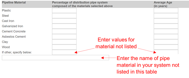
In the first column, enter the estimate for the length of pipe composed of the listed material as a percentage of the total length of pipe in the distribution system. For example, if the estimate is ‘X%’, enter ‘X’ in the blank.
In the second column, enter the average age in years for the corresponding listed material. If information is available, calculate the average using the following method:
Assuming that the total pipeline length for your distribution system is ‘L’, if your system has pipeline length ‘L1’ of age ‘A1’; length ‘L2’ of age ‘A2’ and so on, the average age for that material will be:
If your system has pipe material that is not specified in the form, please use the blank provided below the columns to specify the material, and use the last rows to enter the percent composition and age values, as shown in the image below.
Nominal diameter of a distribution pipe is the internal diameter of the pipe.
PRESSURE MANAGEMENT
Pressure management is a technique that optimizes pressures in a water distribution system to minimize losses and surge impacts while maintaining adequate water service, including fire-fighting flows.
District Metered Areas are created by closing existing or installing additional valves to hydraulically isolate and area. It is a small zone of the distribution system, typically encompassing between 1000 and 3000 customer service connections, with measured supply input flow of sufficiently small volume that individual leakage events can be quantified, thereby guiding leak detection deployment decisions.
Pressure zones are sectors in a distribution system that are established to comply with pressure requirements throughout the distribution system efficiently.
Pressure Managed Areas are parts of a District Metered Area (DMA) or whole DMAs that are subject to pressure management by installing a pressure-reducing valve at the inlet.
Note: Pressure zones where pressure reduction is being practiced to reduce real loss reduction should be included.
Real losses include leakage from mains and service connections and storage tank overflows. It is defined as the physical water loss from the pressurized system and the utility’s storage tanks, up to the point of customer consumption, which is the customer meter in those utilities that meter their customers. In unmetered systems, the delineation is the point at which the customer is responsible for customer service connection piping maintenance and repairs.
Critical pressure points are locations with lowest pressure in a pressure zone or Pressure Managed Areas of the water distribution system, due to topography and/or hydraulic frictional losses in the system.
F. Real Loss Reduction Measures
- Listening devices are equipment which are used to listen for leaks in the distribution system. These typically include, but are not limited to mechanical and electronic listening sticks or rods which are placed on pipe fittings, hydrants or service connections and mechanical and electronic geophones (ground microphones) that are used to listen to leaks from the ground surface.
- Leak Noise Correlators detect the leak sound from the water main or pipe through a receiver unit and two sensors equipped with a radio transmitter, and provide information on the location of the leak. These equipment are placed on valves or hydrants on each side of the suspected leak.
- Leak Noise Loggers indicate the presence of a leak without providing a location. These sensors are permanently or temporarily installed at fittings in the distribution system and programmed to monitor noise indicating leakage at night. The data can be collected by radio transmission.
- Tracer gas technique: Gas (not soluble in water, such as hydrogen or helium) is introduced into an isolated segment of a water pipe, and used to detect a leak through which the gas escapes and permeates to the surface of the pipe.
- Ground Penetrating Radars use radar pulses to find leaks by detecting cavities created around the pipe, leaked water under the surface or disturbed ground.
- Advanced Metering Infrastructure are metering systems that measure and centrally store detailed information on water consumption at frequent intervals, without the need for dispatching crew to customer meter locations. The metering system typically consists of a meter reading device, control system, communications and data management hardware and software between meters and peripheral devices and the utility’s business systems. The nature of this network’s installation is permanent.
- Leakage management software: Software solutions to collect or use distribution system data to process distribution system data to determine water loss levels and possibly provide recommendations to reduce water loss.
- District Metered Areas
- Automatic Meter Reading is where the water consumption is read by handheld devices from meters by personnel in the field or utility vehicles travelling past the customer meters.
- Night Flow Monitoring is a technique used to quantify leakage in a District Metered Area by measuring flows into the area between the hours of 2 am and 4 am, when the consumption is typically the lowest.
- Step Testing involves isolating sections of main from the zone and the zone meter that is recording the flow or pressure on data loggers. It is performed by gradually closing a valve on the input supply main (the input flow is channeled through only one main) and measuring successive pressure or flow reductions in an isolated zone or District Metered Area of the distribution system.
- Visual surveys involve inspecting the ground above the distribution pipelines for surfacing leaks (wet spots) or unusual green growth patches, especially in arid regions.
- General surveys (also known as ‘hydrant survey’) involve installing leak noise loggers at every hydrant in the distribution system and or main valves if no hydrant is present at the desired intervals.
- Comprehensive surveys involve installing leak noise loggers at every available fitting on distribution mains and service connections.
- Repair: This includes repair of pipes and fixtures in the distribution system for which the water supplier is responsible.
- Replacement: This includes replacement of pipes and fixtures in the distribution system for which the water supplier is responsible.
Comments: Enter comments on the Real Loss Reduction Measures implemented. Please specify the measures implemented if possible.
References
- American Water Works Association. 2016. M36 Water Audits and Loss Control Programs, Fourth Edition. Denver, Colorado: American Water Works Association
- Paul Fanner, Reinhard Sturm, Julian Thornton, Roland Liemberger, Stephen E. Davis and Tanya Hoogerwerf. 2007. Leakage Management Technologies. Project#91180. Water Research Foundation
